Project Overview
The structural performance of a gearbox is fundamentally tied to the stress distribution and mechanical integrity of its components under load. In this project, a full-scale stress and strength analysis was conducted on the gearbox of a passenger vehicle, with the objective of evaluating the mechanical behavior of its gear pairs, shafts, and housing components under nominal and peak load conditions.
The primary objective was to ensure the gearbox’s ability to withstand operational loads without exceeding allowable stress thresholds, fatigue limits, or safety margins prescribed by industry standards. Gearboxes are exposed to complex combinations of torsional, bending, and contact loads, particularly at the gear teeth and shaft interfaces. Failure in any of these zones may lead to reduced efficiency, noise, or catastrophic breakdown.
Accordingly, the analysis process in this project followed a step-by-step methodology starting with precise modeling of the gear geometry, loading conditions, and boundary constraints.
Load Spectrum and Initial Calculations
Given the complex interactions between torque, rotational speed, and gear geometry, the first step in the project was to define the load spectrum based on representative driving scenarios. Torque peaks, dynamic transitions, and duty cycles were mapped out to simulate realistic loading conditions over the gearbox’s operational life.
The initial conceptual validation was done using analytical calculations based on AGMA (American Gear Manufacturers Association) and ISO 6336 standards, which provide guidelines for evaluating contact stress, bending stress, and safety factors in spur and helical gear systems.
Modeling Tools and Methodology
To ensure accuracy beyond first-order approximations, finite element analysis (FEA) was employed. A range of engineering software platforms was initially reviewed to determine the most suitable tool for this application. Among the tools considered were KISSsoft, Romax, MecWay, and SolidWorks Simulation.
Based on the geometry complexity, need for standard compliance, and integration with CAD, KISSsoft was selected as the primary analysis tool. Its built-in implementation of ISO 6336 allowed for efficient modeling of gear pairs with precise parameter control, including helix angle, face width, center distance, and load sharing between teeth.
Finite Element Analysis (FEA) Results
In this analysis, boundary conditions were defined to replicate realistic operating scenarios, including engine torque input, resistive drivetrain loads, and structural constraints at shaft supports and housings.
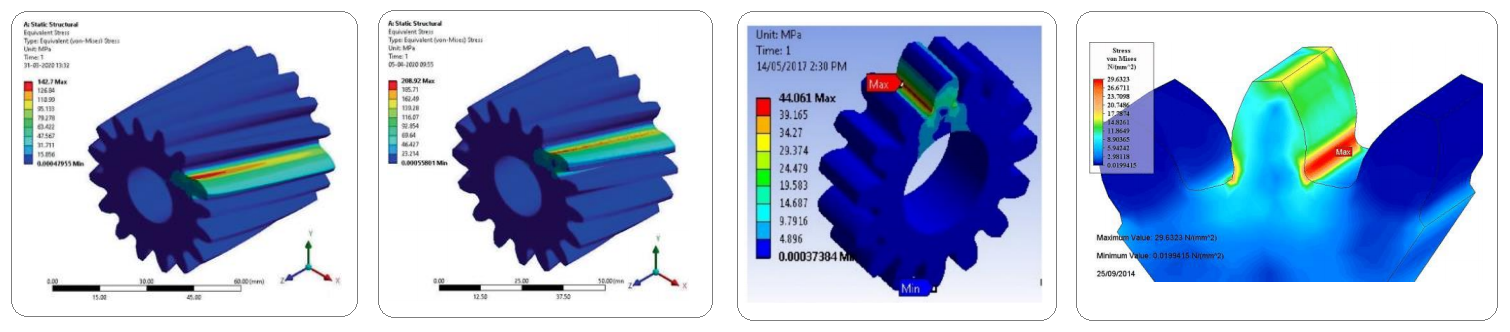
The modeling workflow incorporated detailed steps such as gear geometry extraction, definition of the torque spectrum, selection of gear materials based on fatigue criteria, and consideration of lubrication and misalignment factors. Critical performance metrics—including von Mises stress distribution, gear flank contact pressures, and bending stresses at tooth-root fillets—were calculated using three-dimensional finite element analyses featuring localized mesh refinement in regions susceptible to stress concentrations.
Shaft performance was evaluated for both torsional stiffness and bending response under combined loading conditions. Finally, visualization of stress distributions and gear contact patterns enabled the clear identification and targeted mitigation of potential transmission failure points.
Standards and Material Inputs
International gear design and validation standards were referenced throughout the process, including ISO 6336, which provides detailed guidelines for calculating contact stress, bending stress, and safety factors for cylindrical gears. The material properties used in the analysis were derived from heat-treated alloy steels commonly employed in automotive gear manufacturing, ensuring relevance to real production scenarios.
Fatigue Life & Safety Factor Assessment
To improve result confidence, analytical cross-checks were performed using AGMA-based equations for gear bending and surface durability, along with fatigue life estimation as a post-processing step employing Goodman and Soderberg criteria, particularly focusing on gear tooth root stresses.
Computed safety factors were evaluated against AGMA minimum thresholds, demonstrating satisfactory agreement and compliance with both bending and contact fatigue requirements. Specifically, under peak loading conditions, safety factors exceeded 1.8 for contact fatigue and 2.0 for bending fatigue, confirming that the modeled gear design met or surpassed required mechanical integrity thresholds for both standard and overload scenarios.
Conclusion & Key Takeaways
In conclusion, the project provided a validated stress analysis workflow that can be reused for similar gear design evaluations. The integration of simulation with CAD geometry, adherence to global standards, and dual-method validation contributed to a robust assessment of the gearbox’s strength under operational demands.